PI Engineering Inc.
- Automations
- Controls
- Electrical Engineering
- Professional Service, Infinite Solutions
Lightning Notification Systems
PI Engineering has successfully integrated our remote annunciator system with lightning notification systems (LNS) in several airports and facilities throughout the US and Canada. Most of these are interfaced to a Vaisala based lightning warning system. We build each system in house and can customize it for to meet customer requirements and ease of installation. Successfully completed systems include the following:
- Pittsburgh International Airport
- Philadelphia International Airport
- Tampa International Airport
- Fort Lauderdale International Airport
- Tulsa International Airport
- Charlotte International Airport
- Winnipeg International Airport
- Washington Reagan International Airport
- NASA Johnson Space Center
- Quebec City International Airport
- Montreal International Airport
- West Palm Beach Airport
- Wilmington, NC Airport
- Orlando
- Dallas Fort Worth Airport
- Chicago Ohare
- St Louis Airport
Current projects:
- San Juan Airport
- Austin International Airport
- JFK International Airport
- Washington Reagan International Airport expansion
Component Overview
Web Relay Interface Panel-
The purpose of a remote annunciator system (RAS) is to alert personnel of weather related danger in a timely manner. The RAS consists of an interface panel that connects to a lightning notification system (LNS) to automatically initiate activation of remote annunciators located throughout an airport or facility.
For internet based lightning notification systems, the interface panel connects to a network via a standard RJ-45 Ethernet cable. The panel would be set for DHCP eliminating the need for static IP addresses and would need access to the internet. The panel has redundant communications modules that are always connected to two independent Vaisala Servers. Thus, if one server is not reachable for any reason, the other provides weather data with no downtime. The panel makes outgoing remote services connections to the Vaisala servers, no incoming connections are needed which increases security. This connection to Vaisala’s Web based system would then activate the panel automatically based upon the weather conditions.
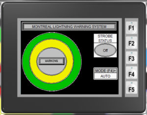
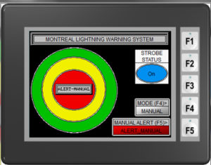
If the LNS is on a local server, the interface panel will connect to Vaisala’s relay panel to provide automatic alerts. The interface panel has a 6-inch touch panel that displays the RAS status. It also allows manual operation of the RAS locally or optionally over the customer’s LAN via any web browser, with proper security (username and password). The panel can also send out email notifications that the system has been activated, alarm conditions such as server communications loss, UPS battery low, and keeps a log of activations. Additional 6-inch display panels can be located anywhere on the customer’s LAN to provide system status or manual operation. The Vaisala/PI Engineering solution gives lightning notification within a couple seconds, sometimes instantly. The Interface Panel can activate the remote annunciators in numerous ways or in combinations. First, the Interface Panel can activate the RAS hardwired directly, each remote unit would need to be hardwired back to the Interface panel. Second, the Interface Panel can activate the RAS over a new or existing Ethernet network. Third, the Interface panel can activate the RAS wirelessly via 900 MHz transmitter/receivers. These three methods are described in more detail be
Remote Annunciators-
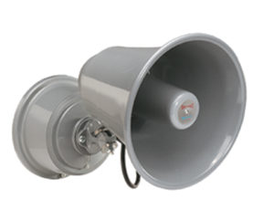
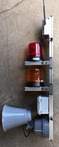
The purpose of the remote annunciators is to alert personnel working at a facility in a timely manner to take appropriate action when a weather event occurs. They also notify personnel whenever the weather event has passed and is safe to return to work. The remote annunciators are customized to meet the specifications of the customer and are activated by either the Ethernet module or wireless transmitter/receiver. Remote annunciator units can also be controlled by a interface panel directly via hardwired connection. They typically consist of one to three colored rotating beacons for visual warning and optionally a siren/horn for audible warning. Rotating LED beacons are used because of their high visibility in all light conditions with minimal power. A 120 Db horn can be heard in noisy environments with minimal power. Aluminum channel is typically used as a mounting base which allows easy mounting to existing light poles or building surface. Optionally, a non-penetrating roof mount can be utilized for mounting the equipment on a rooftop. Typically, the beacons match the Vaisala warning colors (Amber & Red). They can be activated in a manner to meet requirements.
LAN Ethernet Modules-
The LAN activation can utilize new or existing network infrastructure to disseminate the activation signal. Each remote annunciator has an Ethernet module with a 24VDC power supply that receive the activation signals and activate the remote annunciators. The Ethernet module is hardwired to the remote annunciator to activate the beacons/sirens.
Wireless-
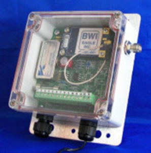
The system can be wirelessly activated by a 900MHz spread spectrum industrial band based radio transmitter that requires no FCC licensing. The wireless system consists of a radio transmitter that connects to the Interface Panel via a twisted pair cable. The transmitter can wirelessly activate, via receivers, any number of remote annunciators located at various locations throughout the facility up to a 20-mile radius line of site. An antenna for the transmitter would be located on the roof of the facility and connect via a coaxial cable (Max length 120 feet). The transmitter would broadcast the activation signal with clear line of site throughout the facility grounds. Wireless Receivers would be located at each beacon/siren assembly. The receivers also act as repeaters creating additional line of site connectivity to other receivers that may not have direct line of site to the main transmitter. The Receivers can have external antennas connected via a coaxial cable for situations where the receiver cannot be located in line of site such as inside a building. Portable receiver units are also possible for use at remote airport construction/maintenance sites. The battery powered portable units are wearable by personnel and have an audible and visual alert.
Power Options-
The interface panel and the wireless transmitter requires a reliable 120 VAC power source. Since this equipment is typically located in an office type environment, power is not a concern. If power is not on a reliable circuit a UPS should be utilized. Each remote annunciator location requires either 120 VAC, 24 VDC, or 12 VDC, reliable power. If power is not already available at a location, then conduit and wire would need to be installed. This can be quite expensive based on facility requirements, engineering, and how far from a power source the location is. To eliminate this expense a solar/battery power source is available. Since the remote annunciator is in a standby mode (no beacons or sirens activated only the receiver is on) the majority of the time, the load is very small. The solar panel charges the battery during the daylight hours keeping the system ready if a weather event occurs. The solar power source has other advantages also. The entire remote annunciator can be prewired and just anchored in place at each location. There is no need for facility drawings or major changes to mounting locations.
Power Options-
The interface panel and the wireless transmitter requires a reliable 120 VAC power source. Since this equipment is typically located in an office type environment, power is not a concern. If power is not on a reliable circuit a UPS should be utilized. Each remote annunciator location requires either 120 VAC, 24 VDC, or 12 VDC, reliable power. If power is not already available at a location, then conduit and wire would need to be installed. This can be quite expensive based on facility requirements, engineering, and how far from a power source the location is. To eliminate this expense a solar/battery power source is available. Since the remote annunciator is in a standby mode (no beacons or sirens activated only the receiver is on) the majority of the time, the load is very small. The solar panel charges the battery during the daylight hours keeping the system ready if a weather event occurs. The solar power source has other advantages also. The entire remote annunciator can be prewired and just anchored in place at each location. No facility drawings or very few need changed, no conduit or wire needs run, etc.
Example of Operation-
(Note:) that this example can be modified to satisfy requirements) Remote Annunciators – The purpose of the remote annunciators is to alert personnel working at a facility in a timely manner to take appropriate action when a weather event occurs. They also notify personnel whenever the weather event has passed and is safe to return to work. Typically, the beacons match the Vaisala warning colors (Amber & Red). Suggested operation, note that this can be altered to satisfy requirements. Warning (Amber) – Lightning has struck within a three-mile radius. Personnel should remove headsets. Alert (Red) – Lightning is within a 3-mile radius. Personnel should stop work and take appropriate cover. Optionally, a siren can be utilized for the Alert mode for an audio signal in addition to the visual beacon. When in auto mode the red beacon will be activated/deactivated automatically from the Vaisala Lightning Warning System and remain on until the alert has cleared. The siren will initially sound a series of six 3 seconds on and 2 seconds off tones for the alert then remain off until the alert has cleared at which time a 10 second continuous tone will sound indicating personnel can return to work.
Systems Equipment
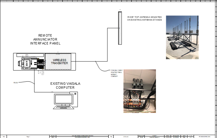
- Interface Control Panels- Proposed Location: At a LNS in the airport control center (ACC). This panel will be mounted in the 19-inch rack that currently holds the Vaisala LNS computer equipment. The control panel will interface to the existing Nvia two dry contacts, one for a amber alert (10-mile radius) and one for red alert (3-mile radius).
- Note, it has not yet been verified if these contacts exist or need to be added and associated costs are not included in this quotation.
- The interface panel will also connect to the LNS PC computer via an RS232 cable and a windows application installed to monitor and manually control the RAS.
3. The interface panel will also connect to a 900MHz Transmitter with an antenna to be located on roof of the ACC with the coax cable routed through existing conduit. This will wirelessly activate the remote beacon assemblies located throughout the airport.
Transmitter/ Antenna
2. Beacon and Siren Assemblies- Beacon and siren assemblies consist of a 900MHz wireless receiver, one amber beacon, one red beacon, and a horn prewired and mounted to a 5-inch aluminum channel.
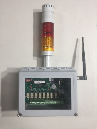
3. Indoor Breakroom/Office Receivers- Indoor receivers with light tower and buzzer will be located in the airfield operations building and have a rooftop mounted antenna to also act as a repeater for remote beacon assemblies that have poor line of site to the main transmitter.
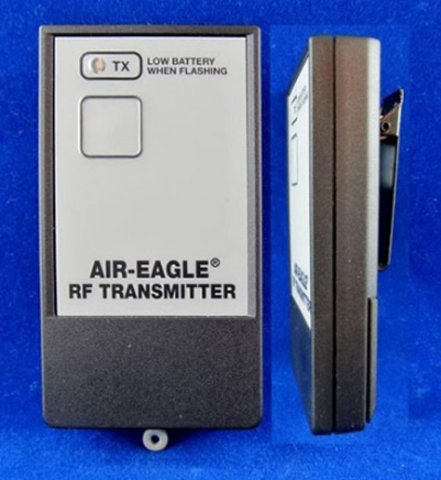
4. Portable Wireless Receiver / Transmitter– Optionally, a portable personnel wireless receiver is available. This unit runs on a battery for run up to 30 days. When activated it vibrates and illuminates a corresponding LED on the unit based upon warning level. Can be utilized for construction/maintenance crews or any other personnel throughout the facilities grounds. Also, optionally available is a hand held transmitter (the size of garage door opener) that can activate a single wireless receiver unit up close for troubleshooting.
5. Mobile Vehicle Mounted Beacon Assembly– Optionally, a mobile vehicle mounted beacon assembly is available. Typically consists of a truck roof mount panel and dashboard on/off switch and indicating lights.
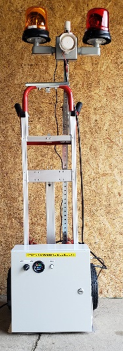
6. Mobile Cart Mounted Beacon Assembly– Optionally, a mobile cart mounted beacon assembly is available. Typically consists of a wheeled cart with beacons and UPS. This is typically used for temporary construction/work areas where LNS is not visible
Systems Overview
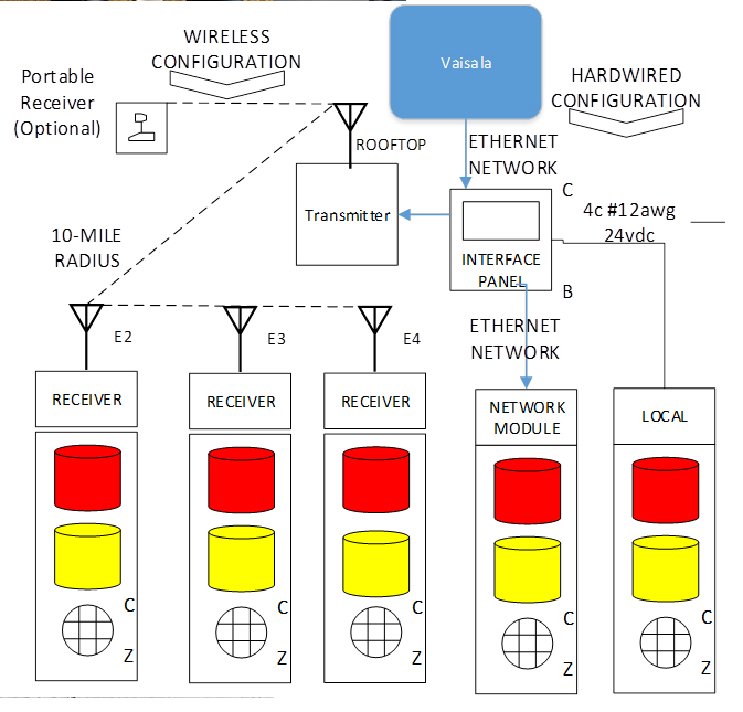
Below are three different methods of activating the remote units. Any one or any combination of the three can be implemented.
- Hardwired Configuration– Each airport will have an interface panel located in the operations center or similar office. The interface panel can sit on a desk or attached to a wall in plain view. The panel would be connected to an existing Ethernet network capable of accessing the internet. interface panel would be powered by a standard uninterruptable power supply sized to run the system for up to eight hours or plugged into a reliable power circuit. The interface panel can control several hardwired beacon/horn assemblies directly via 24 VDC cable within 1000 feet. This method would require running conduit which can be costly.
- Network Configuration– Each airport will have an interface panel located in the operations center or similar office. The interface panel can sit on a desk or attached to a wall in plain view. The panel would be connected to an existing Ethernet network capable of accessing the internet. Interface Panel would be powered by a standard uninterruptable Power Supply sized to run the system for up to eight hours or plugged into a reliable power circuit. The Interface panel can control 16 network based beacon/horn assemblies via network Ethernet relay modules. The interface panel can activate up to 256 network based beacon/horn assemblies with the addition of an advanced Interface option. Each remote unit would also require a 24 VDC power supply and 24 VDC cable, up to 1000 feet. This method could require running conduit which can be costly.
- Wireless Configuration- Each airport will have an interface panel located in the operations center or similar office. The interface panel can sit on a desk or attached to a wall in plain view. The interface panel would be powered by a standard uninterruptable power supply sized to run the system for up to eight hours. The panel would be connected to an existing Ethernet network capable of accessing the internet. The interface panel can control unlimited beacon/horn assemblies wirelessly via a 900 MHz transmitter within a 10-mile radius. Each remote beacon/horn assembly would have a 900 MHz receiver and a power source, either solar or existing 120 VAC. An antenna would be installed on the rooftop of the operations center via coax cable. This method has more equipment costs but can be substantially less expensive to install.
Design Site Visit/Engineering – It is recommended that PI Engineering, Inc. perform a site visit to determine the best, most economical system design. This will enable us to support all questions and provide drawings and documentation for your project approval process and assure ease of installation.
Installation – All components of the system come pre-wired and need mounted to the desired locations of the customer’s facility. Minimal conduit/cables may have to be run based upon the configuration selected. Installation along with any conduit/cable will be the responsibility of the customer. PI Engineering will provide guidance for the installation and final connections as necessary.
Yearly Maintenance – A yearly maintenance service can be provided for the system. This will consist of a yearly visit scheduled for the most convenient date for the customer and PI Engineering as well as 24/7 call support included in the pricing. The visit will consist of two site visits complete system walk down, preventative maintenance, system test, and any possible software updates.
Contact Info:
PI Engineering Inc.
2110 McLean Street
Aliquippa, Pa 15001.
Phone:
(724) 203-0624
Email:
pi@piengineeringinc.com

